The "Array" command in AutoCAD is used to make multiple copies of objects. Although you can use the copy command to duplicate objects, the array command is more flexible and precise. One advantage of using the array command is that it allows you to copy objects in a defined angle and exact number of copies. Therefore, you can create array in various pattern. For example, you can show multiple objects in a row, column, or irregular pattern such as a spiral. Let’s look at a few examples below:

To create an array of objects follow the steps below.
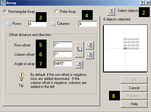
Rectangular Array
1. Type Array in the command line or select  from the modify toolbar.
2. Select the object you would like to array.
3. Input the number of rows. (negative number for downward array).
4. Input the number of columns. (negative number will point array to the left).
5. Pick or input the distance for the Row offset.
6. Pick or input the distance for the Column offset.
7. Enter the Angle for the array. (Use the default 0 degree).
8. Select the Preview button to see the sample array before you hit the Ok button. You can accept the array or modify it. (Optional step).
See the figure below for visual step by step instructions.
Polar array
1. Type Array in the command line or select ![]() from the modify toolbar.
from the modify toolbar.
2. Select the object you would like to array.
3. Enter or select the center point of rotation for the object.
4. Select a method of array. (3 methods to choose from see terms definitions below).
5. Enter the number of items to array. (Methods 1 and 2).
6. Enter the array angle. (Methods 1 and 3).
7. Enter the angle between the objects. (Methods 2 and 3).
8. Make sure to check “Rotate items as copied” if you would like to copy the objects as selected.
9. For Object base point use the default selected. (Optional step).
10. Select the Preview button to see the sample array before you hit the Ok button. You can accept the array or modify it. (Optional step).
See the figure below for visual step by step instructions.

Terms definitions:
Rows and columns: where you enter the number of rows and columns of objects. There is a maximum number of rows and columns that can be entered. If you want to override that number you can always do that by typing (setenv “MaxArray “####”) in the command prompt. Where ### is the new maximum number you would like.
Method of array: There are three (3) ways you can array objects.
(1) Total number of items & Angle to fill. This method will automatically calculate the angle between the items based on the number of items and angle to fill.
(2) Total number of items & Angle between items. This will automatically calculate the angle to fill the array based on the number of items.
(3) Angle to fill & Angle between items. This will automatically calculate the number of items for you based on your input angle to fill and angle between the items.
(4) Base point: is the reference point where AutoCAD will rotate the object. By default, depending on the shape, the base point is already set. For example, a circle, an ellipse, or an arc, they all have a default base point at the center, but you can manually specify a different point.